Category: General Operation

All general hort articles on sprayer operation.

  • Centrifugal and Diaphragm Pumps

    Centrifugal and Diaphragm Pumps

    Press Play to hear the audio version of this article

    Adjusting Sprayer Settings

    Operators are encouraged to adjust airblast sprayer settings to conform to the variability in canopy size, density, spacing, and weather conditions. The efficiency and accuracy of the application is improved through the regular and independent adjustment of travel speed, nozzle output, and air settings.
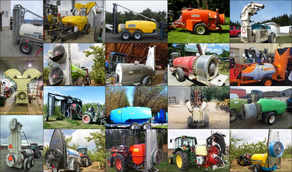
    Airblast design is highly variable.

    Inflexible sprayer design results in a suboptimal match between equipment and crop. For example, sprayers intended to blow across multiple rows in a single pass are promoted for their high productivity, but typically compromise either coverage uniformity or drift control. In another example, low volume mist blowers utilize high speed air to atomize spray and are promoted as a means for saving water and/or pesticide. But, for many such sprayers, moderating air speed to reduce drift potential causes undesired changes to spray quality.

    Even with geared fans, many of Ontario’s airblast sprayers are overpowered for vines, canes, bushberries and high-density orchards. I am uncomfortable with manually obstructing the air intake or adjusting fan blade pitch for safety reasons. Fan gears and travel speed are excellent means for adjusting air energy. Alternately, we have sometimes had success reducing air energy by gearing the tractor up and throttling down (GUTD), but it’s only for very specific situations.

    It has been my experience that centrifugal pumps on axial airblast sprayers can undermine adjustment efforts when spraying small to medium sized canopies (i.e. not tree nut or citrus). In the case of GUTD, slowing the fan reduces pressure at the nozzle. Modest pressure regulation may be possible, but typically the operator must swap to larger nozzles to maintain flow. Hollow cone nozzles are only available in large flow increments (average 0.5 gpm), and stepping-up often results in excessive flow. The operator may be able to increase travel speed to compensate, but this frustrates the original intention by affecting dwell time: air settings must now be reconsidered.

    Within this context, why do some Ontario airblast operators still choose airblast sprayers with centrifugal pumps? Let’s consider Ontario’s Georgian Bay area, which many manufacturers, distributors and mechanics refer to as “the last bastion of the centrifugal pump in Canada”.

    Remember as you read on, Ontario’s airblast crops are predominantly small to moderate sized canopies. Centrifugal pumps are a common and appropriate pump for large canopies like tree nut and citrus.

    Airblast Pumps (in Ontario)
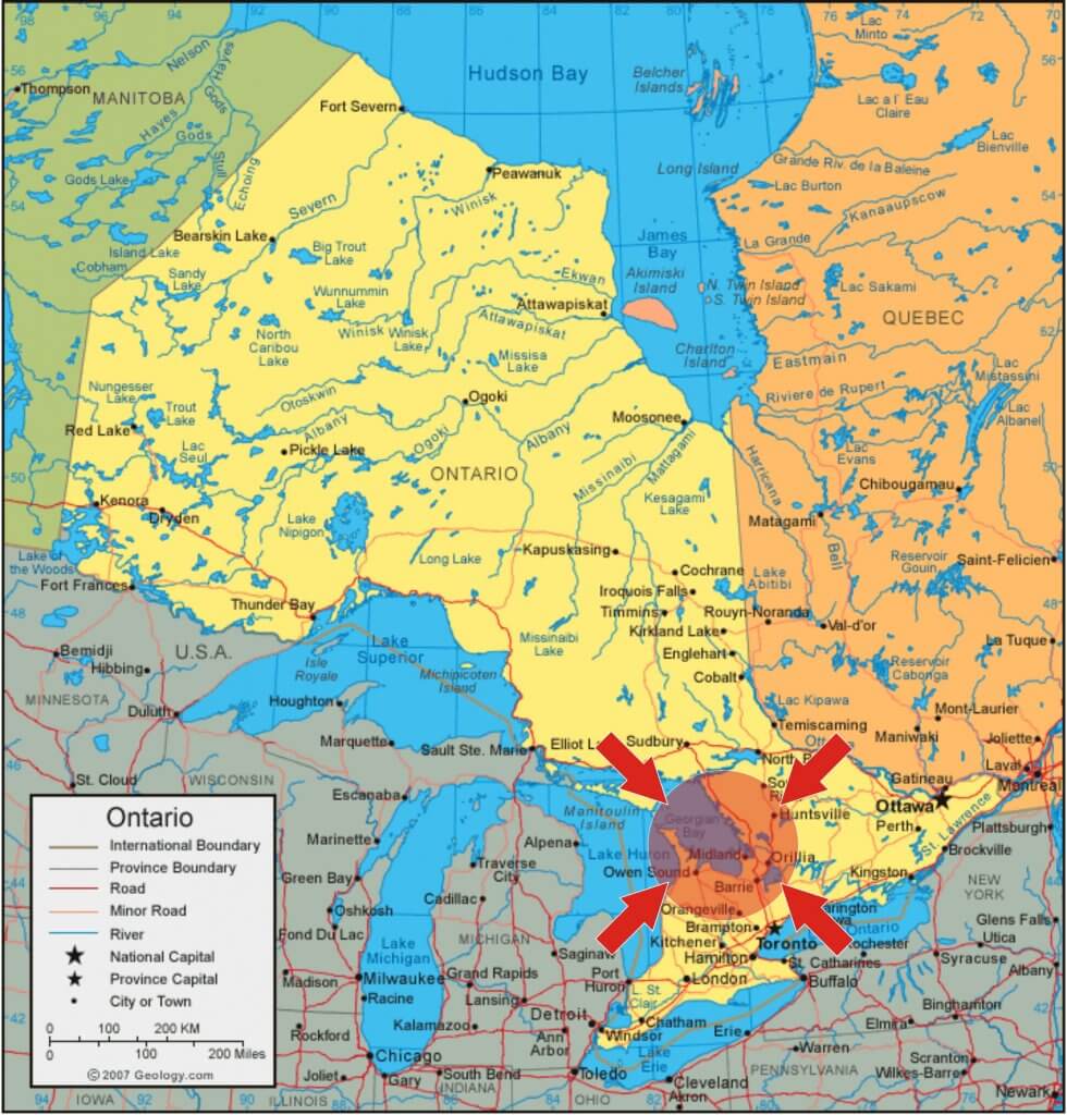
    The Georgian Bay region of Ontario.

    Airblast sprayer design is highly variable, featuring a diversity of pump styles. Piston (or plunger), peristaltic, tractor-hydraulic driven centrifugal pumps are but a few. Historically, piston pumps and centrifugal pumps on John Bean and FMC sprayers were the airblast norm in Canada.

    In the 1950s, Georgian Bay was home to Swanson Sprayers (now part of DW), who manufactured airblast sprayers featuring the Myers centrifugal pump. The sprayer was a good fit for the standard apple orchards found in the region. Huge canopies required high volume applications, and the rough and craggy bark harboured mites that drove the need for drenching sprays. To achieve this, sprayers traveled at 5 km/h (3.1 mph) on 7 m (24 foot) spacing, operating at 10 bar (150 psi) to emit as much as 3,750 L/ha (400 US gal./ac). At the time, a diaphragm pump could not manage this, even traveling at 0.8 km/h (0.5 mph).
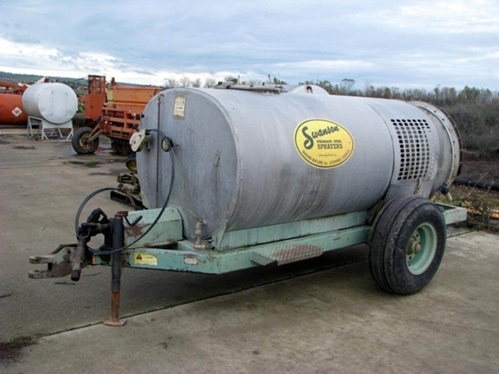
    A Swanson Sprayer (This one likely from Georgia, USA).

    By the 1970s Holland’s Kinkelder air-shear sprayer (centrifugal pump) was introduced to Ontario and promoted as a way to use less pesticide. Perhaps ahead of their time, they never really took off because orchards were still too large for their concentrated (i.e. low-volume) applications. By the 1980s a wave of Italian-made sprayers (e.g. the Good-Boy or GB) featuring diaphragm pumps were imported into the Niagara region by distributors such as Rittenhouse.
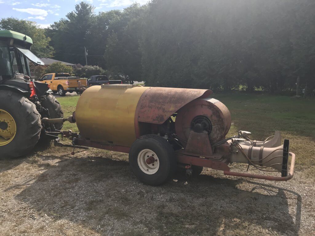
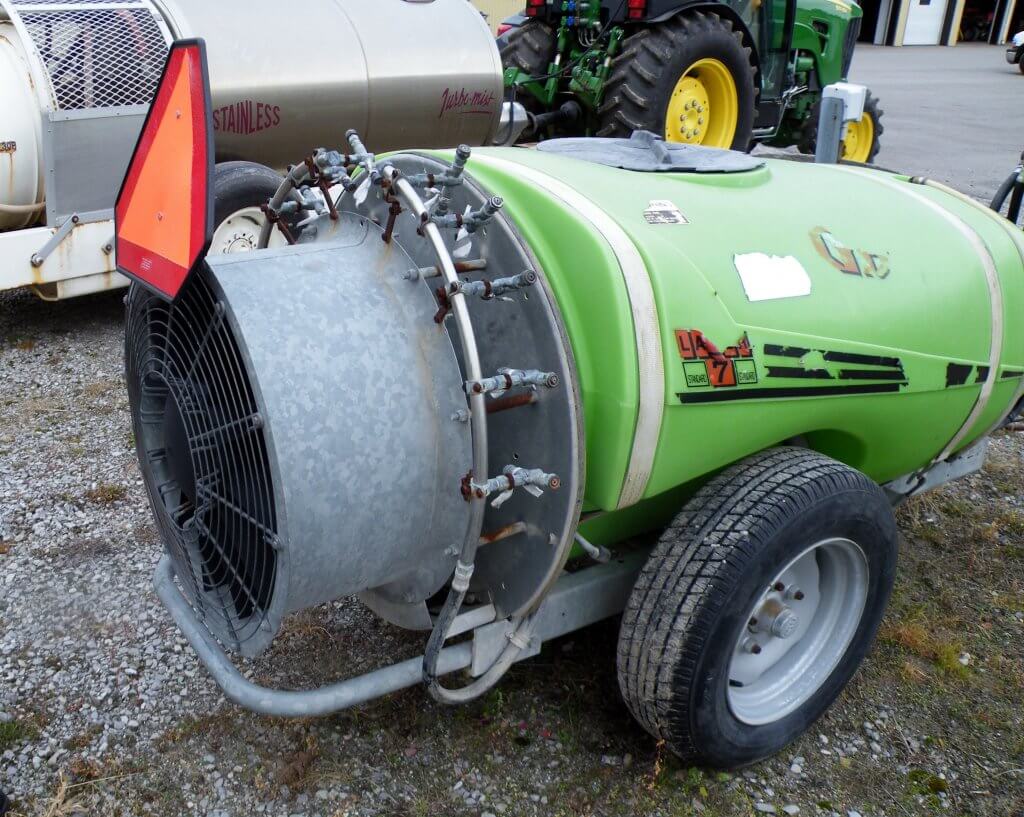
    Similar to the Kinkelder, this was one of Ontario’s last KWH air shear sprayers. RIP 2018.
    The Italian-made Good-Boy (or GB).

    There were many cases of misuse as unfamiliar operators failed to grease direct-drive diaphragm shafts, ran the throttle beyond 540 rpm or diverted flow intended for agitation to increase flow to the booms. Decreased agitation in relatively large tanks left concentrated spray mix to clog suction filters and destroy the diaphragm pumps. It was an inauspicious start, but the diaphragm pump rallied and today we estimate that 90% of Ontario’s airblast sprayers have diaphragm pumps, while the rest are mostly centrifugal. One Ontario airblast dealer claims to sell 50 diaphragms for every centrifugal, but not in Georgian Bay.

    Is it regional history or a long memory of diaphragm “growing pains” that propagate the demand for centrifugal pumps? Perhaps considerations of maintenance, expense or ease of use play a role. Dealers claim that the centrifugal pump is cheaper, but these savings are offset by custom installation costs. Perhaps weather conditions or the crop morphology make centrifugal a better fit? Let’s consider the relative benefits and limitations of diaphragm and centrifugal pumps.

    Design

    Centrifugal Pumps
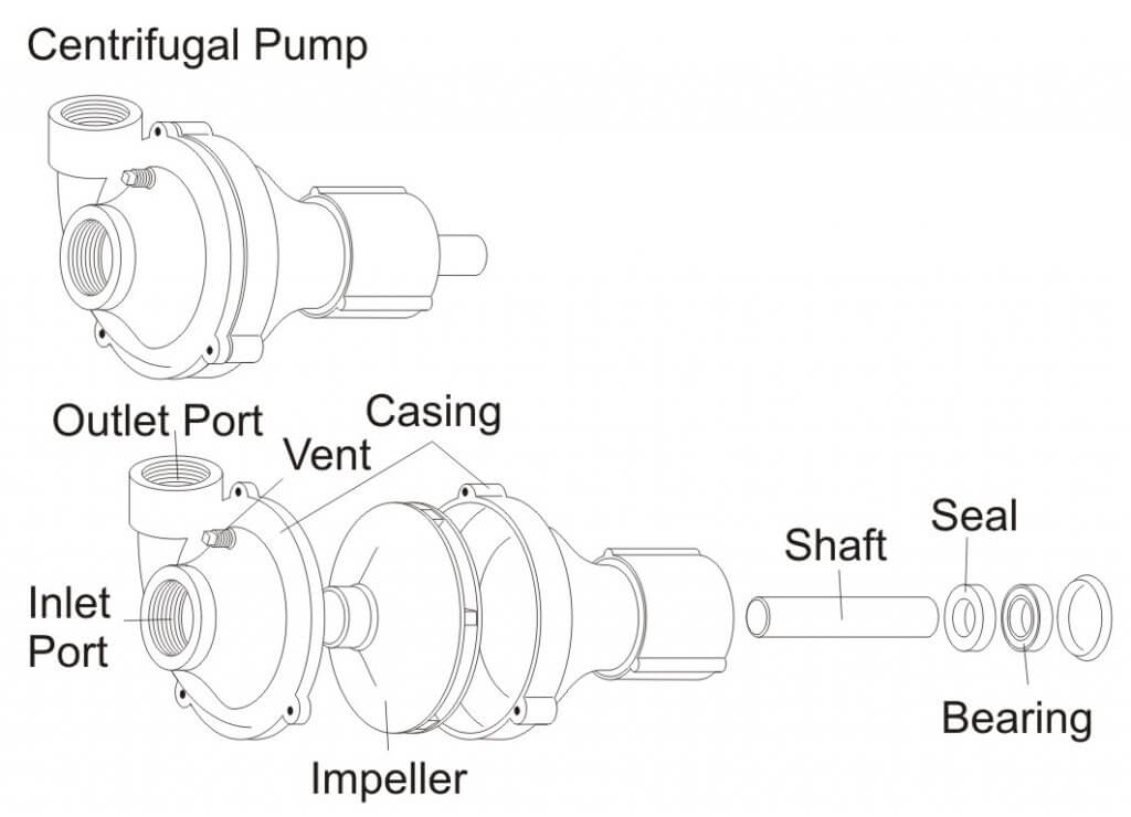
    Centrifugal Pump – Exploded View.

    Most centrifugal pumps prime by gravity feed which is why they are located at the bottom of the sprayer. While less common in Ontario, there are self-priming versions that reserve fluid in the case, or employ clever plumbing, permitting a more accessible location on the sprayer.

    Engine-driven centrifugal sprayers are artefacts in Ontario. The more common PTO-driven impeller operates at high speeds, requiring a >1:4 speed step-up mechanism (e.g. gearbox, pulley or hydraulic motor), and unlike diaphragms, they create smooth flow that does not require pulse suppression. While not technically required, most have a relief valve between the pump outlet and nozzle shut off valve to handle changes in pressure.

    Diaphragm Pumps
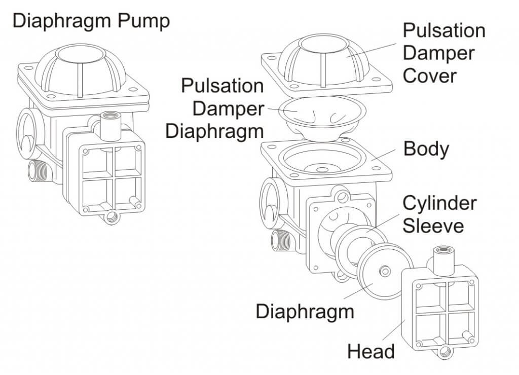
    Diaphragm Pump – Exploded View.

    Diaphragm pumps are self-priming and readily accessible because the shaft runs through the pump to power the fan at 540 RPM, with no need to step-up. Flow is directly proportional to pump speed which in turn depends on the tractor PTO speed. A pressure regulator is used to control bypass flow, which is convenient for making adjustments in nozzle output.

    Pump Flow and GUTD

    Centrifugal pumps are capable of higher flow at lower nozzle pressure and require more horsepower than diaphragm pumps. Note the large relative difference in flow for a centrifugal pump between the operating pressures of 90 and 100 psi (red curve shaded red) versus that of a diaphragm pump (blue curve shaded blue).
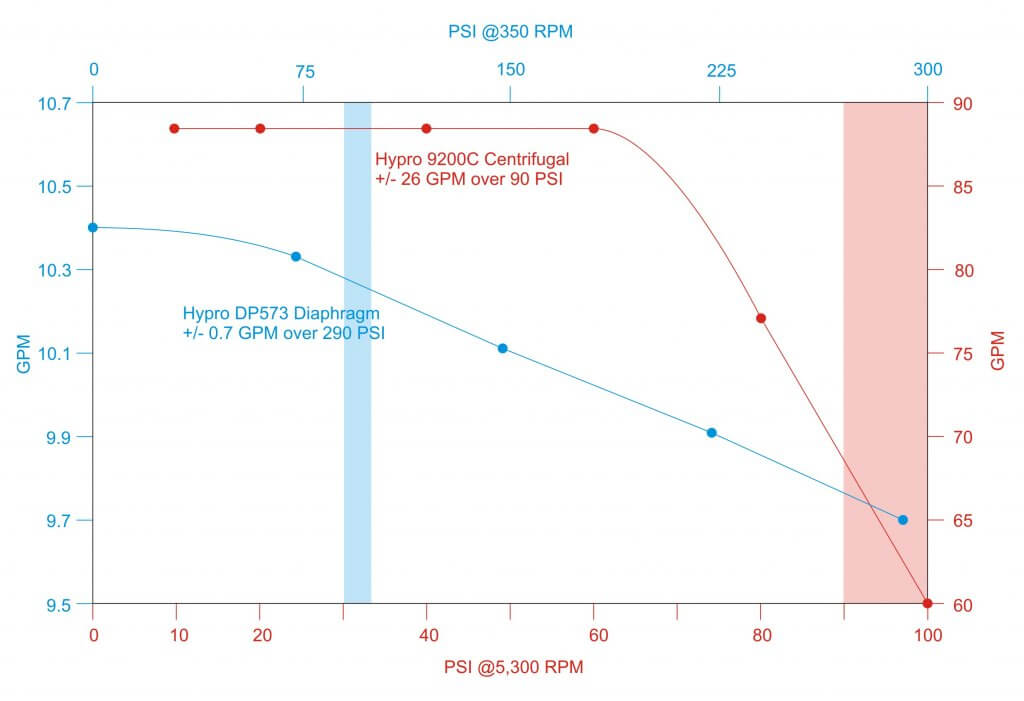
    Relative difference in flow versus PSI at constant RPM for a common Centrifugal (red) and Diaphragm (blue) pump. Shaded pressure represents 90 to 100 psi.

    Centrifugal Pumps

    The flow curve of a centrifugal pump drops off dramatically; pressure (not RPM) dictates flow. If you were to throttle back on a PTO-driven centrifugal pump, reduced flow would reduce the ability to build nozzle pressure. This means fan speed cannot be separated from nozzle pressure, and reducing air speed means re-nozzling.
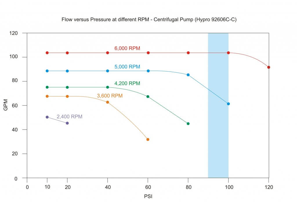
    Centrifugal flow at different RPM. Shaded pressure represents 90-100 psi.

    While (unfortunately) still rare in Ontario, rate control monitors can be used (regardless of pump type) to calibrate output based on a target rate, speed and material flow using travel speed and flow sensors. Nevertheless, they cannot compensate for the aforementioned pressure loss at the nozzle if a centrifugal pump is throttled down to reduce air speed.

    In any case, throttling back on a centrifugal pump can cause a condition called suction or recirculation cavitation (aka pinging). Tiny high-pressure air bubbles form on the suction side of the impellor, explosively pitting the impellor. The damage is similar to corrosion and it causes vibration that will wear the pump prematurely.

    Any restriction on the inlet side (e.g. clogged suction strainer, collapsed/undersized line) can cause a loss of volume that can damage a centrifugal pump. “Dead-heading” (i.e. closing the outlet) is possible for a short period of time, but it quickly results in heat build-up which can cause damage.

    Diaphragm Pumps

    The flow curve of a diaphragm pump is flatter and more efficient; RPM (not pressure) dictates flow. If you slow the airblast fan by throttling the PTO below 540 rpm, flow decreases moderately, but surplus capacity allows sufficient flow to the nozzles without pressure drop. As long as the tractor does not lug, there is less noise, lower fuel consumption and therefore operator can typically adjust the air without having to change nozzles. Even if the flow changes the pressure regulator on the diaphragm pump can be used to adjust nozzle operating pressure, precluding a change in nozzle size. Convenient.
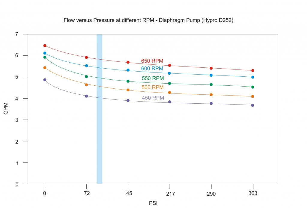
    Diaphragm flow at different RPM. Shaded pressure represents 90-100 psi.

    Diaphragm pumps are capable of high pressure, but are rarely operated above 150 psi in Ontario. Molded hollow cones (eg. TeeJet’s TXR or Albuz’s ATI) operate well in the lower psi range compared to pressure-loving disc-cores. Therefore, while regulators and springs are sized according to the pump’s maximum settings, they do not reflect the usage pattern. The relatively heavy spring is too stiff to compensate for changes in pressure (e.g. driving on hills or closing one boom) behaving more like a fixed bypass and undermining a calibration. The phenomenon is discussed more detail in this article.

    Maintenance

    Centrifugal Pumps

    A centrifugal pump with self-lubricating bearings and quality seals (e.g. carbide) that is maintained seasonally and operated in the best efficiency point of the curve will run reliably for many years.

    Proponents of the centrifugal pump claim they are low maintenance (compared to the diaphragm pump). This may be anecdotal, because of the pump’s out-of-sight position on the sprayer and their tolerance for neglect. A mistreated centrifugal pump fails by degrees, often forgotten until a seal leaks or a pressure drop is noticed. In the later situation, increased flow from nozzle wear can mask the problem as the sprayer continues to cover the same number of hectares. Often overlooked, worn or misaligned sheaves/belts on a centrifugal sprayer can also cause a loss of flow. Operators might notice a tail breeze that blows spray onto the belts can cause slippage and lower the nozzle pressure.

    Diaphragm Pumps

    Opinion is divided on the longevity and maintenance of diaphragm pumps. Some claim they are reliable and low maintenance as long as regular oil changes occur. Others suggest the complication of connecting rods, o-rings and valves require more upkeep than the simpler centrifugal. Unlike the centrifugal pump which merely loses pressure, failure on a positive displacement pump is complete and requires immediate repair

    Much depends on the diaphragm material and the products being sprayed. For example, corrosive materials (e.g. copper sulfate, urea, etc.) require polymer manifolds to minimize contact with metal. Metal manifolds do not weather well.

    The diaphragm pump can run dry for extended periods. This creates heat but does not often lead to failure. Failures occur from exposure to vacuum, which can happen with dirty suction filters or long and/or improperly sized suction lines, or even lack of oil support on the compression stroke (caused by over-revving).

    While three-cylinder designs may not require pulsation dampening, most require an accumulator to suppress the pulsing created by each stroke. Improper adjustment can lead to “hammering” that cracks mounts and valves, and can exacerbate rub-points on hoses. Diaphragm pumps that use direct drive shafts (i.e. carry the PTO to the fan) are subjected to the thrusting of the drive shaft during turns. It is important to keep them greased.

    Summarily, the longevity and maintenance requirements for either pump design seem about equal. They depend on the products being sprayed, the quality of pump materials, and adherence to the manufacturer’s instructions on correct usage and preventative maintenance.

    Conclusion

    Ontario’s airblast-specific crops have become smaller, closer and denser. High liquid volumes and air speeds are typically not required. Operators are encouraged to use Crop-Adapted Spraying to adjust fan speed and nozzle output to the crop and the weather. In my opinion, the diaphragm pump facilitates this, resulting in lowered input costs, reduced drift and improved coverage uniformity. I recognize that this requires skill and effort on the part of the operator, and setting-and-forgetting a centrifugal pump can be attractive, but it’s unacceptable if it leads to unnecessary environmental impact.

    In the end, the sprayer manufacturer chooses the pump, atomization and air-handling system while considering safety, effectiveness, reliability and price point. The operator must acknowledge the capabilities and limitations of the sprayer design when choosing the best fit for their operation.

    I still don’t know why regions like Georgian Bay seem to prefer one pump over another. Perhaps it’s simply herd mentality. Perhaps they know something I don’t. But consider: an airblast sprayer’s average lifespan is 30 years. That’s a long time to live with a decision.

    Choose wisely.

    Special thanks to the many dealers, manufacturers, engineers, mechanics and end-users that helped to inform this article.
  • Spray and Soil Fumigant Buffer Zones in Canada

    Spray and Soil Fumigant Buffer Zones in Canada

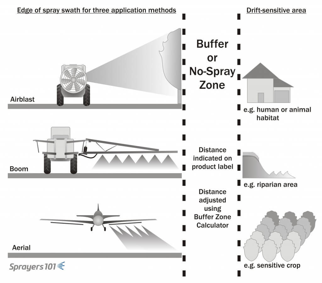
    Spray buffer zones are no-spray areas required at the time of application between the area being treated and the closest downwind edge of a sensitive terrestrial or aquatic habitat. Spray buffer zones reduce the amount of spray drift that enters downwind, non-target areas.

    Sensitive Terrestrial Habitats

    Sensitive terrestrial habitats can include hedgerows, grasslands, shelterbelts, windbreaks, forested areas and woodlots. Crops and private properties adjacent to treated areas are not considered to be sensitive terrestrial habitats and do not require spray buffer zones. However, labelled spray buffer zones are a good indicator of potential damage to adjacent vegetation. Applicators are responsible for ensuring their spraying programs do not adversely affect neighbouring properties.

    Sensitive Aquatic Habitats

    Sensitive aquatic habitats can include lakes, rivers, streams (channelized or natural), creeks, reservoirs, marshes, wetlands and ponds. Temporary bodies of water resulting from flooding or drainage to low-lying areas are not considered sensitive aquatic habitats. Nor are aquatic drainage ditches or seasonal water courses that are dry at the time of application. Water body depth will determine the buffer zone distance, as indicated on the pesticide label. Downslope open water may also require a vegetative filter strip .

    The pesticide label will indicate when a spray buffer zone is required. The distance will depend on the product used, the method of application and the crop being sprayed. In some cases, the buffer zone may be modified using Health Canada’s Spray Buffer Zone Calculator . When provincial and label restrictions differ, or label restrictions differ between tank mix partners, use the greatest distance.

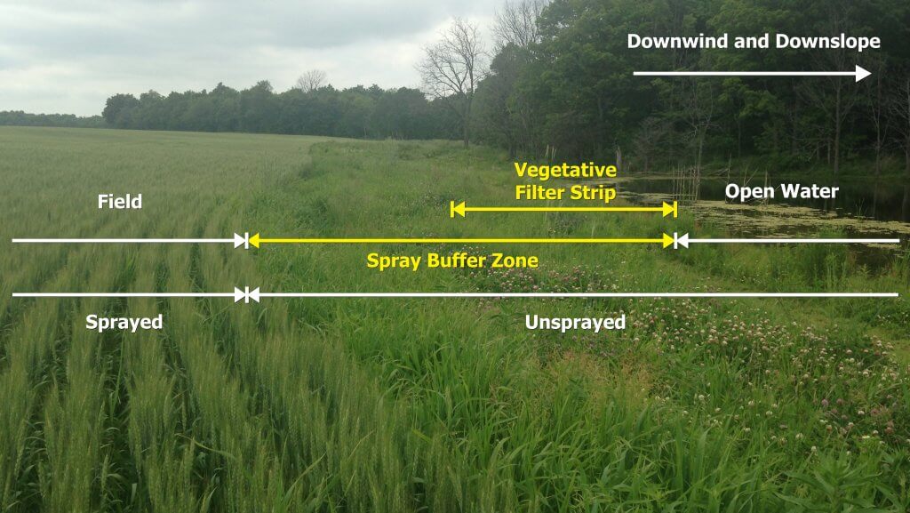
    Buffer zones or No-Spray zones physically separate the end of the spray swath for the nearest downwind sensitive area.
    Buffer zones or No-Spray zones physically separate the end of the spray swath for the nearest downwind sensitive area.

    Spray Buffer Zone Calculator

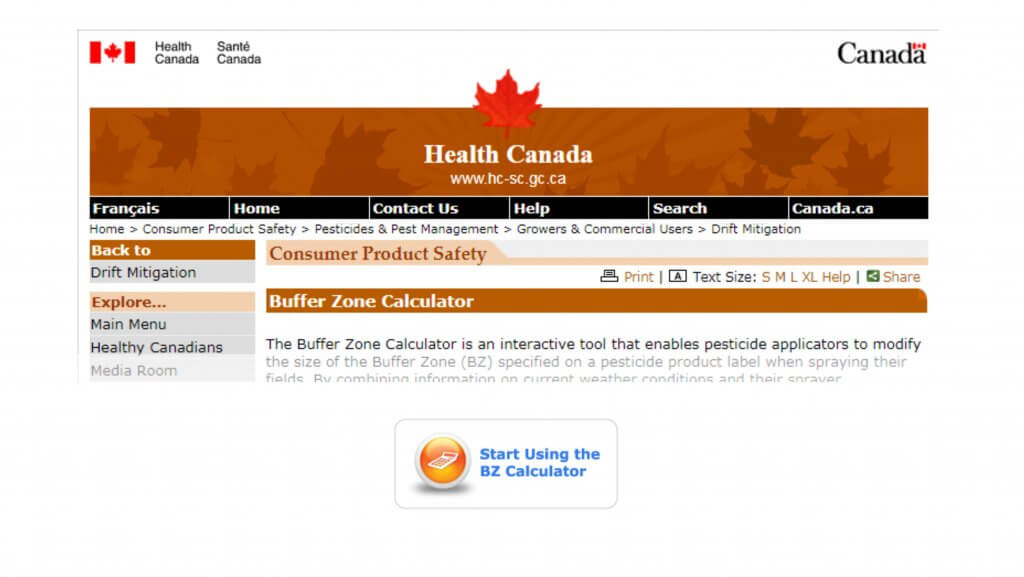
    Unless forbidden by the pesticide label, Health Canada’s Spray Buffer Zone Calculator may permit applicators to reduce the size of the spray buffer zone specified on a pesticide label. To be eligible, the product label must specify a field or aerial spray quality coarser than “Very Fine” and finer than “Very Coarse”. All airblast spray qualities are applicable.

    Modifications are based on meteorological conditions, sprayer configuration and the application method at the time of application. If modified spray buffer zone distances are less than provincial or municipal distances, use the greater distance.

    Applicators that choose to use the calculator must retain a copy of the summary page for at least one year following the application to demonstrate compliance with label directions.

    Vegetative Filter Strips

    A vegetative filter strip is a permanently vegetated strip of land that sits between an agricultural field and downslope surface waters. Vegetative filter strips reduce the amount of pesticide entering surface waters from runoff by slowing runoff water and filtering out pesticides carried with the runoff.

    Pesticide labels may require a vegetative filter strip, or recommend one, as a best management practice. They must be at least 10 metres wide from edge of field to the surface water body and be composed primarily, but not exclusively, of grasses.

    Spray buffer zones do not apply to vegetative filter strips unless there is a pre-existing sensitive terrestrial habitat within them. Therefore, vegetative filter strips may overlap spray buffer zones when open water is both downslope and downwind (see illustration). In this case, the minimum 10 metres vegetative filter strip distance must be observed, but the set-back can be larger based on spray buffer zone, provincial or municipal restrictions.

    Soil Fumigant Buffer Zones

    Soil Fumigant Buffer Zones are mandatory, untreated perimeters surrounding the treated field. They limit user exposure and increase the protection of workers, bystanders and the environment. The distance will depend on the application method, product rate and field size, as indicated on the pesticide label. An Emergency Response Plan is required when residences or businesses are located within 90 metres of the buffer zone perimeter.

    Soil fumigant buffer zones have a time component. This Buffer Zone Period begins at the start of the application and ends a minimum 48 hours following the application. Respiratory protection and stop-work triggers, as specified on the pesticide label, will apply to anyone present in the buffer zone area during the buffer zone period.

    Buildings and residential areas within the soil fumigant buffer zone must be unoccupied during this period. Unless in transit, non-handlers (including field workers) must be excluded from the soil fumigant buffer zone during this period. Entry is permitted for fumigant handlers with appropriate certification, emergency personnel and local, provincial, or federal officials performing inspection, sampling, or other similar duties.

    Image from www.onspecialitycrops.ca

    Soil fumigant buffer zone signage must be posted within 24 hours prior to the application and remain posted until the buffer zone period expires. Signage must include, but is not limited to, the date and time the buffer zone period ends and the name, address, and telephone number of the applicator. Soil fumigant buffer zone signage must be located at the outer perimeter of the buffer zone, at all entrances to the field, and along likely routes where people not under the owner’s control may approach. Soil fumigant buffer zone signs are in addition to, and do not replace, fumigant application block signage .

    Applicators must develop a written Fumigation Management Plan prior to the start of any application. The plan outlines key steps to ensure a safe and effective fumigation, including site conditions, buffer zones and emergency response planning. Both the owner/operator of the fumigated area and the fumigant applicator must retain signed fumigant management plans as well as a summary of Post-Application Procedures for two years following the application.

  • How Much Horsepower do I Need?

    How Much Horsepower do I Need?

    How much horsepower (HP) do you need (really) when pairing a tractor and a towed sprayer or any other PTO powered implement? This important question should be asked BEFORE purchasing any towed implement. Surprisingly, there’s not much guidance out there, so you might hear answers like:

    1. Whatever my tractor has must be enough… whatever that happens to be.
    2. What?
    3. The right amount of HP is what I can afford. Erma, grab that milk can full of egg money… 
    4. MOAR! (Yes, we know how “more” is spelled, but memes are funny).
    Skeletor knows horsepower

    Rating Tractor Horsepower

    If you thought there was only one way to rate the horsepower of a tractor, well, you’d be wrong. At its simplest, horsepower is:

    (torque × engine revolutions) ÷ a constant

    We’ll expand on this later. The rub comes in how you define each of these factors and where you measure the power. Let’s start with something simple like engine speed, which is expressed in Revolutions Per Minute or RPM’s.

    Engine Speed

    So, if horsepower is the result of torque times engine speed, what speed do the manufacturers plug into the formula? One of two values are used:

    1. Power Take-Off (PTO) Engine Speed

    This is the engine RPM’s that produce the rated operating speed on the PTO. When the PTO is engaged, the engine is directly and mechanically connected to the PTO shaft. Therefore, maintaining the engine at the rated PTO speed, typically between 1,500 and  2,300 RPM depending on if it’s gas, diesel, turbocharged or not, will keep the PTO spinning at a uniform 540 or 1,000 RPM (the two typical PTO speeds) regardless of the driving speed.

    2. Maximum Engine Speed. 

    This is the engine’s maximum intermittent operating speed… just shy of destroying said engine. An engine rated using the maximum speed gives you a false sense of security, because to get that horsepower you’ll be burning a ton of diesel, over-speeding your PTO implement, and wearing your tractor out very, very quickly. You wouldn’t drive your car around town in low gear because you’d redline the engine. Why would you do it to your tractor?

    In the speedometer/tachometer (above the steering wheel) on this beautiful old tractor, the first black bar is the PTO rated RPM. The second is PTO Max. Operating with the PTO engaged above PTO Max can be damaging to the implement and to the tractor, and dangerous for the operator.

    Horsepower Basics

    OK, now we are ready to dig in a little deeper into defining tractor horsepower. What does it mean if, for example, your tractor is rated at 65 HP? We’ll skip the history lesson on watching the output of horses over an average day and move to the modern definition. Horsepower from a rotating shaft (such as the output of an engine) is:

    Horsepower = [Torque in foot-pounds × Engine speed in Revolutions Per Minute (RPM)] ÷ 5,252

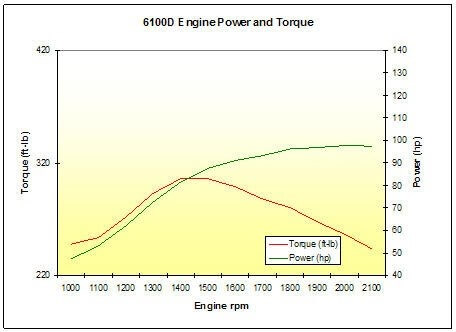
    Here is a typical tractor torque curve. Notice how after peak torque, RPM’s climb quickly but net HP doesn’t. Unless specified, we can assume this is Engine Horsepower, not PTO Horsepower. If the above Torque/HP curves were your tractor, the PTO speed would likely be 1,500-1,600 RPM. According to the graph that would equate to about 82 HP. Running the engine up by 40% (2,100 RPM which is the max speed in this case, gets you about 98 horsepower. That’s only a 20% improvement. Remember, this is engine horsepower, not PTO horsepower, so this may not all be available for you to use. Image from JD.

    Total Versus PTO Horsepower

    Perhaps our tractor’s 65 HP rating describes Engine Peak Horsepower. This is what the engine would produce on a test stand, and it likely uses the maximum engine speed. This rating is a bit disingenuous. Not only because you will probably operate it at rated PTO engine speed, but also because some power is lost to internal processes, like the power steering pump, automatic transmission pump, alternator, auxiliary hydraulics, et cetera. So peak engine horsepower isn’t usually a very useful number unless you are in marketing and like big numbers.

    A more accurate and useful rating is the Power Take-Off (PTO) Horsepower. This is the amount of horsepower available to do work at the PTO shaft. This may be at the rated PTO engine speed or the PTO Maximum speed. Estimating power using either speed offers a much more realistic rating of what you have to work with. As previously noted, PTO Rated Speed is usually near the speed where the engine creates the highest torque per revolution. This is often called the Power Band. Operation in this engine speed range will use the least diesel and result in the greatest amount of life in the machine. 

    Another important thing about PTO Horsepower is that this is the total amount of power available to do work. This could all go to PTO when the tractor is standing still, but both locomotion and the horsepower required to run the implement need to be subtracted from this number. So if your tractor is indeed 65 PTO horsepower, that’s the actual amount of horsepower you likely have to work with in real life. 

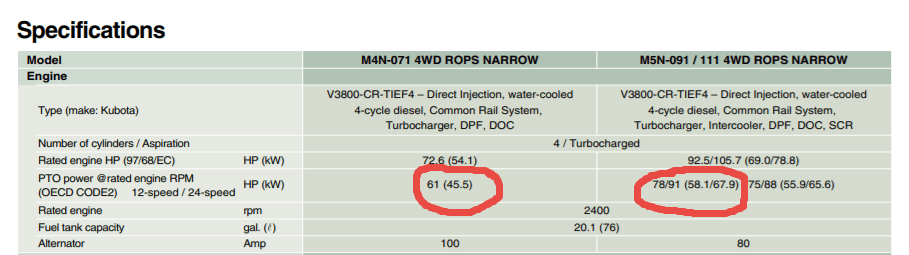
    In this excerpt from a Kubota Spec sheet, you see that the Rated Engine horsepower is quite a bit higher than the PTO horsepower. A 72 HP “rated” tractor really has 61 horsepower for you to work with. The 106 horsepower version on the right really has 91 PTO horsepower.

    The Horsepower that Matters

    To sum things up, PTO Horsepower is the number you really need to care about. All this up to now just to describe the nuances of how horsepower is expressed. No wonder HP is a topic that’s avoided. If you can find or download the manual, now you at least have the tools to get to how much horsepower you have to work with.

    Maximum Load

    In order to answer the question of how much HP you need, you must consider your operation. You need to size your tractor for the biggest load it will ever be used for, even if you only do that thing once a year. Typically this would be a sprayer, rotavator or a brush flail. The rest of the year you won’t burn much extra diesel if you aren’t using the power in a bigger tractor, but you can’t draw on horsepower that isn’t there in a smaller one. 

    Though it’s not common, you can have too big a tractor.  You need only watch “Clarkson’s Farm” for ample evidence (and a chuckle).

    The enormous and infamous Lamborghini tractor that starred in “Clarkson’s Farm” on Amazon Prime is a good example of taking horsepower a little too far.

    The Basics of Estimating Load

    Now that you have the extremes in mind, let’s get to scratchin’. There are three things you must know to determine the maximum load: 

    1. Locomotion – The power needed to move the tractor and implement
    2. Implement Power – The power needed to operate the implement
    3. Safety Factor – This is a buffer that gives us a little extra just in case.

    For the following guesstimates let’s assume you are doing orchard and vineyard work with a compact/narrow tractor. There really aren’t any hard and fast equations for this, but these will get you in the ballpark. If you are a nut grower with full sized tractors or a vegetable/field crop grower, you may need to scale up. 

    Locomotion

    People discount it, but the power required just to move the tractor and the implement around is substantial. If the implement is a fixed tower sprayer with a 500 gallon tank, this might require 15-20 HP on flat, dry land. If your topography includes hills, or your terrain includes mud or tall grass, you may need to double that requirement. 45 HP just to move around before you even engage the PTO. Speed matters, too; If you are driving 5 mph, you’ll need twice the HP versus driving 2.5 mph.

    C’mon Tom! Faster! Redline those RPM’s! Image from www.pigtailpals.com

    Implement Power

    The manufacturer of the implement should be able to tell you how much horsepower the implement requires. Small, three-point hitch airblast sprayers may only require 10-15 PTO HP. Larger tower sprayers may require 40-50 PTO HP. Brush flails may take 25-45 HP.

    This is where things can get sticky and you need to make sure you’re both talking the same language. Some manufacturers will tell you how much power the implement takes, others will skip all the steps in this article and go right to recommending the size tractor they think you’ll need. If you’re unsure, ask. Be sure to factor in the locomotion requirements discussed earlier, the dealer may not understand your conditions in their general recommendation but usually can provide some clarity with a little more information from you.

    Safety Factor

    It’s always a bad idea to run at 100% of your power capability. Most of you reading this article are likely working with mid-life or older tractors with a few thousand hours on them. Ol’ Bessie loses some of the pep in her step over time. After engine break-in, the tractor will slowly lose power capability over its life. The harder you work it, the faster this occurs. Enthalpy happens (now that’s a great tee-shirt idea).  Plan for it. Once you have an idea of your worst-case locomotion and implement power needs, add them up and give yourself another 15% (That is, multiply by 1.15).

    Summing It Up

    Now we can finally answer the question. In order to determine how much tractor horsepower you need, follow these steps:

    1. Understand the real PTO horsepower of the tractor you are considering. This is the only thing that matters. You should be able to find online documentation for this if it doesn’t come with the tractor or you’ve filed it somewhere that you’ll never forget…
    2. Establish the maximum load you are likely to encounter. Calculate this by multiplying the sum of Locomotion and Implement Power requirements by a 1.15 Safety Factor.
    3. If you are still unsure, discuss these factors with your trusted local tractor dealer, ensuring you are both speaking the same language. It is better to err on too much tractor than not enough, but do so within reason.

    Looking at our original orchard application with a 500 gallon tank and a larger tower type sprayer, travelling around 3 mph:

    35 HP for locomotion, 40 HP to run the sprayer and 15% safety puts us at 35 + 40 + [0.15 × (35+40)] = 86.25 PTO HP

    Wishing you all MOAR POWER and perfect spraying weather.

  • Venting Liquid-Filled Pressure Gauges

    Venting Liquid-Filled Pressure Gauges

    Liquid-Filled or Dry?

    Small-plot agricultural sprayers should have a pressure gauge on the wand or boom to ensure accurate application rates. Most are added after-market and the operator has the choice of buying liquid-filled or dry gauges.

    Glycerine- or silicone-filled gauges are preferred because they dampen pressure spikes, pulsation and mechanical vibration. Compared to dry gauges, they are available in higher ranges and are less prone to moisture problems (which cause corrosion, accuracy and visibility issues).

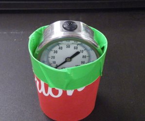
    We use 100 psi (~7 bar) liquid-filled gauges for our handheld sprayers. Only recently did we acknowledge the sticker affixed to the glass advising the user to cut the nipple off the rubber plug located at the top. Preferring to avoid messy leaks, we have always left it intact.

    We wondered what impact, if any, this was having…

    What are Vents?

    Expensive gauges have mechanical vents that can be opened prior to use and closed to retain liquid when stored. More commonly, there is a rubber plug with a protrusion (referred to as a nipple).

    Why Vent?

    Mechanical, liquid-filled gauges are sealed to keep the liquid in. When there are temperature fluctuations, the liquid expands or contracts and creates “case pressure”. This exerts a force that interferes with the pressure reading.

    According to Marshall Instruments, case pressure can offset the accuracy by approximately 1 psi (0.07 bar) for every 35˚F (20˚C) temperature change, but is only noticeable when measuring lower pressures (0-15 psi or 0-1 bar). Nevertheless, they advise all gauges should be vented prior to use.

    The plug can be removed to allow the user to refill the gauge, maintaining an air space of about ½” at the top of the window. If the nipple is cut off, the gauge is permanently vented and will leak if the gauge is not kept vertical.

    Testing

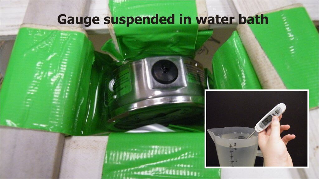
    We performed an experiment to see if typical working temperatures had a practical impact on the accuracy of an unvented gauge. We suspended an unvented, liquid-filled gauge upright in a water bath at approximately 15˚C, 30˚C or 45˚C (59˚F, 83˚F or 113˚F) until it equilibrated. The high temperature may seem unreasonable, but gauges left in trucks on summer days get far hotter.

    The gauge was quickly removed and placed in a manometer (Ametek T-975) where it was subjected to pressures of 15, 30 and 45 psi (1 bar, 2 bar and 3.1 bar) and readings recorded. This was repeated five times. We then vented the gauge and repeated the process.

    Results

    At first, there appeared to be very little difference in average accuracy of vented and unvented gauges. Accuracy refers to the closeness of a measured value to a standard or known value. Perhaps there was some small increase in the pressure reported by an unvented gauge, but very little practical difference.

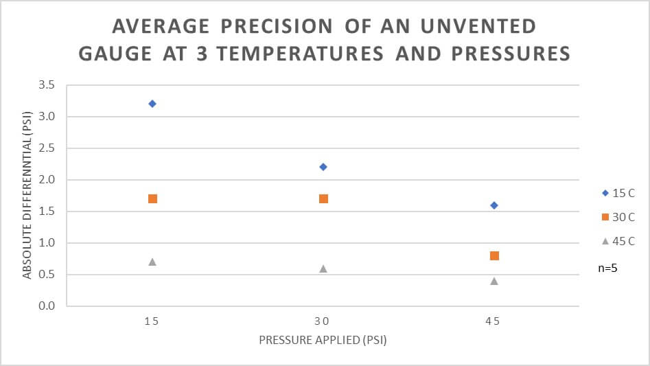
    However, when we look at variability we get a different picture. Variability is a measure of precision, which refers to the closeness of measurements to one another. The graphs show that an unvented gauge has greater variability (less precision) at lower temperatures and lower pressures.

    A good way to think of accuracy and precision is using the classic archery bulls-eye metaphor. The unvented pressure gauge is best represented by the third image, where it is accurate (on average) but not precise (variable).

    Real-World Example

    What does this mean in practice? Consider someone spraying a small plot using a TeeJet XR8002 nozzle on a CO2-powered hand boom at 30 psi. The difference in output between 30 psi and 40 psi is about 0.003 gpm / psi.

    An unvented pressure gauge used on a hot day may read 1.5 psi lower, causing you to overcompensate and raise the pressure 1.5 psi higher than intended. That would result in 0.0045 gpm (0.5%) more applied. Compensating for an unvented gauge on a colder day might be closer to 0.009 gpm (1%) more applied.

    Assuming a walking speed of 3.1 mph (5 km/h) and a swath of 20” (50 cm), the nozzle should emit about16.3 gpa at 30 psi. Unvented in the heat, that’s 16.7 gpa. At 33 psi, that’s 17.15 gpa. That’s almost 1 gpa more than intended. Potentially, the lack of precision could make a significant difference.

    Conclusion

    • Liquid-filled gauges are preferred over dry gauges.
    • To ensure precision, the gauge should be vented prior to use.
    • Permanent venting on a hand-held sprayer causes leaks, which is a nuisance, so we suggest simply lifting the edge of the plug with a screwdriver or fingernail to vent the gauge prior to each use.

    This work was performed by OMAFRA summer student, Aidan Morgan.

  • Oh the Places You’ll Spray – Parody

    Oh the Places You’ll Spray – Parody

    Enjoy our take on a Dr. Seuss work-of-art. We’re sure the fine doctor would want to end resistant pig weed’s reign of terror as much as we do. Hear us recite it in the sound bar, read it yourself, or head to the bottom of the article to see the talented Bridgette Readel (@bmreadel) read it for you. Enjoy!

    Press Play to hear the audio version of this article

    In the home farm’s west field,
    where the soybeans won’t grow,
    and the wind blows the soil from deep tillage you know,
    and no pollinators come, excepting old crows
    is the patch of resistant pigweed.

    And downhill in the boundary, some neighbours say,
    if you look close enough you can still see today,
    where herbicide persisted,
    in the places it drifted,
    from the winds that took it away.

    How did it drift?
    How did it get there?
    And why was it lifted and taken somewhere
    from the home farm’s west field where the soybeans won’t grow?
    Look to the sprayer.
    Look close, and you’ll know.

    You won’t see Coarse nozzles.
    You will see high booms
    that wobble and bounce on a sprayer that zooms
    in headwinds too high
    in the late afternoon.
    They may even spray by the light of the moon!

    Check the chemical shed.
    Crack the door, just a fraction.
    You’re likely to see
    A lone mode of action.

    “Tell me how,” says the farmer
    “I’ll do what you say.”
    “But I only have so many hours in the day
    to spray the west field where the soybeans won’t grow,
    and battle the pigweed that simply won’t go.”

    “Oh the things you can do! So much can be done!”
    “Learn to spray in light winds, in the day, in the sun!”
    “Lower booms, use more water, use droplets so Coarse.”
    “We’ve told you before…
    (you will note we are hoarse.)”

    The farmer said nothing, just gave us a glance.
    We could tell he was thinking of time, effort and cash.
    “Driving slow improves coverage,
    and you can make up the time,
    with faster fills, longer booms, and more precise A-B lines.”

    That was long, long ago.
    Let’s check in today,
    and see if the problems have withered away.

    In the home farm’s west field,
    where the soybeans now grow,
    and cover crops cling to the soil down below,
    the pollinators buzz because drift doesn’t blow.